
| Home | Astronomy Home | My Clear Skies | My Photos | Cool Stuff I Made | Tips & Procedures | My Setup |
| StarPowerCube | Observing Chair | Balance System | Telrad Mount | Flat Field Lightbox | Telrad Pulser Circuit | The Phaser Cam Cooler | The Springy Thingy |
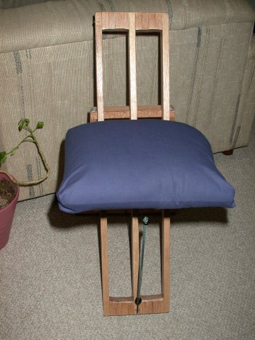
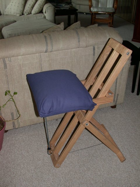
After a few nights as a newbie stooping over to peer in the eyepiece, my back told me to do something about it. I looked for Observer's Chairs available on the market and felt that most were too costly or were not very nice-looking. I came across this design when surfing and felt it was within my limited carpentry skills and budget ($70) to make. Below is the result. My dear wife made a very very comfortable cushion for it. It may look fragile but it easily holds my 200+ lbs.
(Original
design by James Crombie, modified by Dennis Friedman)
Obtain
your construction materials (approximately 24ft of 1X2”) clear hardwood (maple
or oak) or the equivalent (you may want to consider teak or redwood as well).
q
1 - 14 x 10 x ½” plywood (Seat
base)
q 1 - 3’ length of (5/16-18) threaded rod
q 4 - 5/16 x 2 ½” carriage bolts
q
12 - 5/16 washers
q
10 - 5/16 nuts
q
4 - eyehooks
q
4
- #8 x 2”
woodscrews
q
4
- #6 x 3/4
woodscrews
q
1 - 14x l0x 1/4’ plywood
q
1 - 14 x l0 x 2” foam and fabric to suit (a foam cushion will
also work)
q
Glue, varnish or paint to finish
q
1 - ¼” cork strip (one sheet)
q
1 – Bungee Cord – approximately 13”
q
3’ of piano wire or equivalent (strong cord can be
substituted)
q
3
- 1” x 2” x 36’
- main uprights
q
18
- 2” x 2” x
1”
-
fillers between uprights
q
2
-
1” x 2” x 18” -
leg sides
q
1
-
l” x 2” x 16”
-
leg base
q
2
-
1” x 2” x 14”
-
seat sides
q
2
-
1” x 2” x 11 1/16” -
seat
crosspieces
Note: If you are using lumber thinner than 1” you will have to alter your dimensions to suit. You may add filler blocks to widen the uprights
q
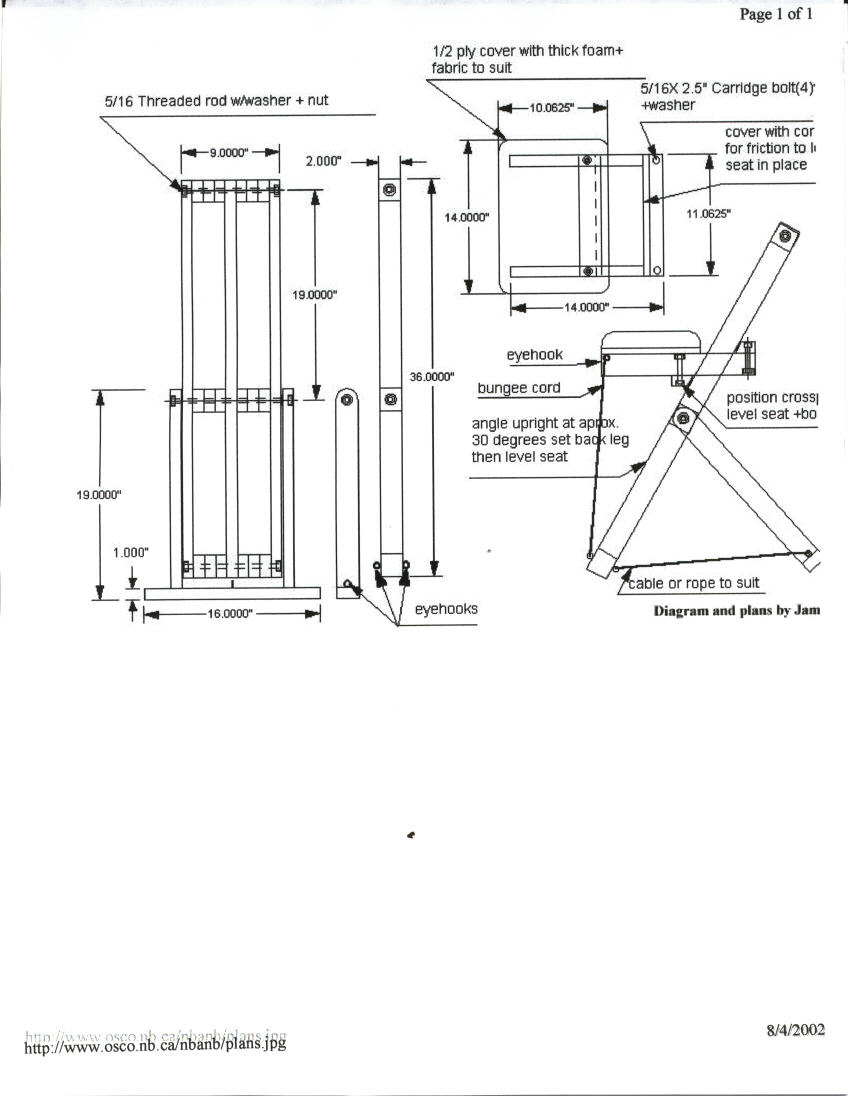
Drill 3/8 holes in the filler
blocks and the main uprights, and counter bore a 7/8” hole, ¼” deep to fit
the washers & nuts in the top and bottom of the 2 uprights, and at the top
of the leg side pieces. Cut 2 pieces of threaded rod 1/8” shorter than the
width of the assembled upright. Cut one piece of threaded rod to fit thru the
legs and uprights with a washer as a spacer between them.
q
Spread glue on all mating faces of
the uprights and spacers. Assemble and use threaded rod to clamp the unit
together. Check that all pieces are aligned and square before final tightening.
q
After the glue has dried measure
the distance to die outside of the legs with the spacer washers between the legs
and uprights. Mark the leg base accordingly. Round
over
the top of the legs before assembling. Drill pilot holes for the #10 x
2” screws and glue and assemble the leg. If you have the tools, dowel the leg
base first.
q
Measure the outside distance of the upright assemblies and add
1/16” to 1/8” to the measurement between the seat sides. This allows the
seat to slide up and down without binding; too much will let the seat get cocked
sideways and may drop. Cut the crosspieces to suit and then cut the bevel on one
side. Drill the holes and counterbores for the back crosspiece, then attach the
seat base and back crosspiece
using glue,
the bolts and screws. After the glue has dried apply the cork (or rubber) to the
bevel of the two crosspieces. The cork provides the friction to keep the seat
from slipping when you sit on it.
q
Trial assemble the legs to the
main upright and set the length of
the cable
to
get the proper 30-degree angle of the upright. Place the seat on the upright so
that it rests on the legs, then set the bottom crosspiece in place so that the
seat is level and mark both sides. Remove the seat and clamp the crosspiece in
position and drill and counterbore the holes for the bolts Assemble with glue
and the bolts but check alignment on the upright before tightening the bolts.
q
If you have a router then use a ¼”
rounding bit to radius all edges or use a block plane. Next, sand all surfaces
smooth and clean off all dust and apply several coats of exterior varnish. Allow
to dry thoroughly and sand between coats (Don’t coat the cork.). After the
last coat has dried, install the eyehooks, cable and seat covering.
Place the foam on the ¼” ply, then stretch the fabric over it and
staple to the bottom. Place this over the seat board and using the ¾’
woodscrews, attach from the bottom. Insert an eyehook at the bottom of the
upright. This puts a little tension to the seat and prevents it from slipping
when you get up. And that’s all!
q
You can alter the dimensions to
suit your application and available materials I have seen several made of metal
tubing. The commercial version is excellent but is rather very pricey.
Suggestions for
modification by Dennis Friedman
q
Replace the 24’ of 1”x2” oak
with a 4’ x 12” x 2” plank. Rip the 2 lengths of 1 ½” strips from the
plank (you make the leg base, leg sides and seat box from these) leaving a board
that is ~ 4” x 9” x 2”. You need to cut this remaining piece to a length
of 3’. The excess can be used for any other wood needs. The remainder will
then form the main structure of the chair.
From this board remove four rectangular sections, which would have formed
the empty space between the uprights and the spacers. I think this would require
much less overall cutting, fitting, and gluing. In addition I believe the chair
might have even greater structural integrity. It also eliminates the need for a
top rod.
q
Use a preformed foam pillow with a
slipcase cover. It will be more comfortable and durable.
q
Consider adding a leg base to the
front structure to add more stability (its pretty stable as is). If you do so
the back legs will not close over this added base. If this is not viable
considering adding a slight angle to the front legs to allow more wood to touch
the ground.